Will Millivolts Reading at Ignition Points Hurt Burn Points

If your bicycle is starting to suffer from blown headlight bulbs or the bombardment's ability to concur a accuse is becoming unpredictable and so you demand to inpect your bikes charging system.
There are three main sections to the charging system on near bikes (excluding the wiring inbetween). Those are the Battery, Regulator/Rectifier (R/R) and the Stator.
The battery is there to power the electrical components of the bike when the engine is not running.
The job of the Stator is to catechumen mechanical energy from the engine dorsum into electricity. The output from the stator on most modern bikes is three stage (hence the iii wires) alternate current at a peak voltage well over the 12-14V DC voltage that your electrical system requres.
The R/R unit converts the alternating electric current (Air conditioning) in the diode bridge rectifier department then regulates the voltage to limit it to around 14V DC where it is fed back into the Bombardment and powers the remainder of the bikes electrics.The voltage is college than the battery voltage so current flows from the R/R unit dorsum to the bombardment to charge it.
Starting time off before you go running through the post-obit tests, if y'all are having any electrical/charging problems then bank check that all electrical terminals/connectors are all tight, free from corrosion and secure. Also audit for signs of either breaks or burning in the wiring or connectors.
To do a thorough test of the charging system or other electrical items yous will crave the use of a Multimeter and/or a 12v Test Light. A Multimeter if used correctly is going to requite you more than accurate results where as a test low-cal will only requite you an guess issue according to either the brightness of the bulb or if the bulb lights up or not.
1. IGNITION OFF
2. IGNITION ON, LIGHTS ON, Bicycle Non RUNNING
3. BIKE STARTED, LIGHTS ON, RUNNING AT FAST IDLE
4. FURTHER TESTS, IGNITION OFF
v. RESISTANCE TEST
6. VOLTAGE Examination
vii. CURRENT DRAIN Test
1. IGNITION OFF
First test the status of the Battery. With the Battery on the bicycle and continued and set your Multimeter to 20v DC. Your basically setting the meter to the side by side nearest number that covers the maximum range that you are testing for. Put the Red probe on the the positive (+) terminal and Blackness to negative (-) earth terminal and check the initial Bombardment voltage. It should read annihilation above 12.0v merely under thirteen.2v just ideally between 12.5 – 12.ix DC volts is required. Any less than this, you lot may showtime to see starting problems as the Bombardment will not accept enough juice to turn the big twin motor over. Virtually of the battery power is required for cranking the engine over from cold.
If the Battery is flat then employ an Optimate or similar slow charger to recharge the battery. The Optimate chargers as well do good from a recovery mode. The slower the charge the improve it is for the Battery long term. Do non use a automobile charger as information technology will shorten the life of the Battery and overheat the internal fluid and cells. Y'all should disconnect the Bombardment if not using the bike for long periods of time and put it on trickle charge. Batteries do discharge slowly over fourth dimension and information technology is not e'er possible to recover a fully discharged Battery.
2. IGNITION ON, LIGHTS ON, BIKE Not RUNNING
With the Battery fully charged and functional it's time to exam for Battery voltage drop. With the Multimeter on the aforementioned settings every bit above. With the ignition on and the bike not running switch on the lights and you should encounter the voltage drib slowly as the lights apply upwardly the power in the Battery. The voltage should non drop much below 12v and should only pass up slowly. If the the voltage drops chop-chop to effectually 11v then the Bombardment has either not been charged thoroughly or it is not holding a sufficient accuse and will need replacing.
3. Bicycle STARTED, LIGHTS ON, RUNNING AT FAST IDLE
Now on to testing the main charging function, the voltage output from the Regulator. Test the voltage with the wheel running at fast idle, roughly between 2000 and 5000 rpm, to confirm if it is getting the correct amount of charge from the bike. With the Multimeter fix to 20v DC place the meter leads across the Battery as before, if all is healthy you should be getting between xiii.five-xiv.5 volts, an old or tired Battery will be around thirteen.2 – 14.8 volts if undercharging or overcharging only is of no great business organisation as of even so, but keep a close eye on things over time to make certain information technology does not deteriorate. Please note that these voltages volition fluctuate depending on temperature and revs.
Rev the bike and the voltage should exist at least in the 13'south at all engine rpm's and become no higher than around 14.5v. If you are reading 15v or higher it is bad and means that the R/R is not regulating the extra voltage from the Stator and overcharging the Battery. This will start to eddy the fluids inside the Battery dry and volition eventually get out y'all stranded as the battery will not be able to hold a charge.
If this is the example then information technology is probable that you will take to replace the Regulator/Rectifier and the Bombardment. This besides works the opposite mode. If the Bombardment is defective, either dried out or has damaged cells from age or electrical faults, the Regulator will output the maximum it tin trying to accuse the Battery back up. If this continues for long periods of time so it can eventually harm the Regulator though heat damage with having to dissapate excess voltage rather than charging the battery. And then even so once more it is likely that you will have to replace the Regulator/Rectifier and the Battery.
Be warned, don't merely get out and supersede either one or the other without checking the other is operation correctly first. Otherwise you could be just treating the symptom and non the cause and get caught in a wheel of either i or the other breaking your replacement. This could go expensive.
Simply concur on…. before rushing out and buying replacements the earth to ground should be checked and ruled out from causing any misleading readings.
The R/R will exist earthed to ground either by the mounting to the frame or a dissever wire. A split wire being the more common of the two. It'southward very of import to have a good solid earth as the Regulator will shunt (short) any excess alternating current (AC) from the Stator before giving the Bombardment the required amount of directly current (DC) . This is why R/R units get very hot equally the internal diodes switch on and off to ground equally they laissez passer high amounts of electric current through them. Excess shunting due to an unhealthy battery puts additional strain on the Stator which tin can result in the coils burning out!
To test that that there is a good earth check and make clean upward all connections, it'south a good idea to use a serrated type washer that digs in to the surface when tightened later previously removing any pigment or powdercoat. Either bare metal or a direct feed to the Battery will give the best connection. Once your are sure the earth is good run through the above voltage output exam once more. If the earth is ruled out and is all good, withal your still getting above 15v then it'south fourth dimension for either a replacement R/R Unit, Battery or both.
With the bike running, lights on, and every bit yous rev the bike the lights should get a trivial brighter as the Regulator puts more voltage back into the Bombardment to charge information technology. If the voltage does not rise at all and the lights don't get whatever brighter then at that place could be a mistake with the positive (+) feed to the Battery via the main fuse, and then don't rule out connections on the Starter Relay behind the left rear fairing or even the Ignition Switch itself.
Then if you are getting a normal charging voltage but when you rev the bike harder the voltage drops, even down to zero, then the Regulator/Rectifier is breaking down under load and will demand replacing. You can also do a quick load examination with the ignition on with the wheel not running and applying the brakes. The Bombardment voltage should drib no more than than around 1 volt with the brakes applied.
4. FURTHER TESTS, IGNITION OFF
Practice a leak to basis test, with the ignition off. Start with either disconnecting the plug from the R/R or the three pin connector block further down that leads to the Stator. This can be found in the main wiring harness connector bundle in front end of the Battery and has three Xanthous wires going into it.
Exam each wire individually with your multimeter fix 20v DC put the Red positive probe on each connector either directly on the R/R outputs or if working from the connector cake in the harness, on each connector pin on the R/R side. So put the black negative probe to earth either on the engine frame or Battery and cheque to see if the meter is reading any excess electric current leakage.
If you take any more than a couple of volts then the diodes inside the Regulator are faulty and assuasive voltage from the Battery to leak to earth. This will also permit current from the Stator side to leak to world so it won't be providing the full amount.
The same test tin also be done on the R/R earth wire or the torso of the R/R itself. To practice this yous will have to disconnect the R/R from the frame and disconnect the earth from either the frame or the Battery if you accept it connected direct. Place the Positive meter probe either on the torso of the R/R or earth wire and the negative probe to world. Once again, if there is more than a couple of volts then you have a problem.
5. RESISTANCE TEST
Next it's time to do a resistance test for no continuity between the Stator coils/windings. This can be washed from the same 3 pivot connector block in the master wiring harness connector package in forepart of the Battery, only you will use the opposite end of the plug that goes dorsum towards the Stator, or you tin take the reading from the R/R connecting cake leading dorsum towards the three pin connector and on to the Stator.
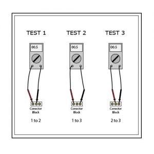
Start turn your Multimeter to the lowest Ohms scale, mine is 200, then touch the probes together to go a resistance reading from the meter. My meter reads 00.ii yours may be a different reading depending on the meter used. Y'all have to recollect this number equally it needs to be deducted from your final reading later.
With engine off and the connecting block disconnected from either the Regulator/Rectifier or the 3 pin cake, examination the resistance on each of the iii Xanthous wires in the following combination 1 to two, 1 to 3 and 2 to 3 as in the following diagram.
For each exam the meter should read between 0.two and 0.5 ohms. If y'all have no resistance or a high resistance between any pair then you need to pull the Stator out and visually inspect it for whatever burnt sections. If a third or more than of it is damaged and then it'south time for a replacement Stator. There may be enough to go along the wheel running, simply every bit presently every bit you use more Battery power upward with lights or accessories the Battery will slowly belch until it somewhen dies.
Too examination the iii Yellow Stator wires for a short to ground/globe. Connect the positive meter probe to i of the three stator connections in the plug and the negative to earth. If y'all meter reads either a 1 or I followed past a decimal betoken then this is an Infinite resistance, meaning no path to ground/earth which is what we want. If you lot have any other reading then one of the Stator coils/windings is grounding out and will not produce as much current as it could and loose the power to accuse the Bombardment. Practise the same examination on all 3 wires.
6. VOLTAGE Examination
Even if Resistance is all good you lot can still have a faulty Stator as a Stator tin can pass the resistance check just fail a voltage check. A voltage output test volition show upwardly if it's producing a reliable electric current throughout the rev range.
For this test you need to set your multimeter to an (AC) alternating current voltage of a minimum of 100v AC depending on how far you test, the lowest setting on my meter is 200v AC which is more than plenty. With the bicycle running and connector block disconnected measure the Air conditioning voltage between each of the 3 Stator connector terminal pins as in the previous resistance test every bit per the diagram above and make a annotation of what they read. Y'all volition have effectually 20v AC or thereabouts at 1000rpm depending on the amperage of the bikes charging system.
The bodily voltages measured is not and then important and they will vary depending on revs. But what is of import is that the three measured voltages are roughly the aforementioned value. A reasonably safe tolerance would exist around -5 or +five of each other, whatever more this would suggest a short in the Stator coils/windings and farther investigation would be required. Also cheque the voltage throughout the rev range as it should rise in increments the higher the revs. For example, at 2000rpm information technology should read effectually 40v Air-conditioning, so double the corporeality of what information technology read at 1000rpm, and so at 3000rpm is should read around 60v AC, 4000rpm it should exist 80v AC and and so on. If there is a weak output or no output at all and then there is a trouble with Stator at higher revs and further investigation is required.
For a thorough test the Stator resistance and voltage checks should both be done when the engine is cold and also when the bike it is at total running temperature. This ensures that you don't miss any faults that may merely bear witness themselves either when cold or hot from the expansion and wrinkle with temperature.
If you lot are positive that the fault lies within the Stator itself then information technology will require the removal of the generator comprehend. Check the Stator for any loose windings, broken wires or signs of overheating and called-for.
7. Electric current Drain TEST
If all above tests prove to be sufficient and you can't find a fault within the charging system and are suffering from a Battery constantly discharging, it could be ane of two things. Starting time you either accept a defective Bombardment.
Sometimes a Bombardment can laissez passer all tests but they can fail in many ways and faults don't always show upwards when testing. Or second, you have another component that is drawing electric current from the bike particularly when everything is switched off and the cycle is sitting overnight. Alarms or immobilisers can be off detail concern here.
A quick test would exist, with the ignition off, disconnect the Battery positive cablevision being careful non to touch the frame with your spanner, or temporally disconnect the negative/world showtime. Connect a 12v test light between the positive cable and the Bombardment positive. If the light comes on then you have something drawing ability. The brighter the light, the more power being drawn. To try and determine which circuit the power is existence drawn from, disconnect the fuses ane past one until the low-cal goes out or dims. Y'all would have and then narrowed it down to only the components within that particular excursion and can investigate further.
A more authentic test would be to use a multimeter set up to direct current amps, not volts. Y'all may accept to move the positive probe to a divide socket on the multimeter. Sometimes there are ii sockets, a loftier range and a depression range. Always test on the highest setting beginning, the highest setting on your multimeter volition more than likely exist 10A Max. The low setting volition exist in milliamps indicated as mA or uA. If by testing on the highest setting showtime and the current draw is less than the multimeter'due south next lowest setting, so it is safe to proceed with moving the positive probe dorsum into the other socket and go on testing.
Practice not start the engine while running this test or put the probes across both Bombardment terminals or y'all run a risk either damaging the multimeter or bravado it'south internal fuse. To start the test first disconnect the Battery negative/world cable. With the ignition off and starting with the highest setting on the multimeter, place the positive meter probe on the cable and the negative probe on the negative on the Battery. Yous will and so see any electric current draw. Where possible select the next highest setting down such as mA or uA and motility the positive probe to the appropriate socket on the meter. This will change the readout from amps to milliamps and give the most authentic reading for a small current draw. The specified current draw every bit standard is 0.01mA . As long as you don't take items on the cycle connected to a permanent Battery feed and switched on like alarms, immobilisers, LED'southward or something then this should not modify, otherwise the reading volition be slightly higher simply should exist no more than effectually 0.03 depending on how many items you take running.
If you have a high current bleed then remove the fuses one by one as before until the current drops to narrow down which circuit the electric current is being fatigued from. An alternative way to run this test would be from the fuses themselves by placing the probes directly beyond each side of the fuse on the circuit being tested.
I think that just near covers it.
Al.
Source: https://www.aberdeenbikers.co.uk/motorcycle-charging-system-diagnosis-checks/
0 Response to "Will Millivolts Reading at Ignition Points Hurt Burn Points"
Post a Comment